

Inquiry
UL 9540A 6th Edition (LSFT) Fire Safety Standards for BESS & Industrial Battery Buyers: Technical Breakdown & Compliance Guide
Executive Summary: To deploy Battery Energy Storage Systems (BESS) or high-capacity lithium battery installations in North America and internationally, meeting ANSI/CAN/UL 9540A 6th Edition (published March 13, 2026) and NFPA 855:2026 is mandatory. The Large Scale Fire Test (LSFT) evaluates whether a fully developed fire in a BESS cabinet propagates to adjacent units or structural walls at specified minimum separation distances. This guide breaks down the 4-level test hierarchy, quantitative pass/fail thresholds, test conditions, and compliance requirements for commercial, industrial, data center, and specialized lithium battery applications.
1. What Is UL 9540A LSFT and Why Is It Required?
Under severe thermal, electrical, or mechanical abuse, lithium-ion battery cells can enter thermal runaway, venting toxic, flammable gas mixtures (H2,CO,C2H4) and triggering fires.
The Large Scale Fire Test (LSFT) under ANSI/CAN/UL 9540A 6th Edition Section 10 physically simulates a fully developed fire in a complete, field-representative battery array. Mandated by NFPA 855:2026 (Standard for the Installation of Stationary Energy Storage Systems), LSFT empirical data verifies:
Minimum Equipment Separation Distances (Distances A, B, C, D in test layouts).
Fire Propagation Limits to adjacent target units or structural barriers.
Efficacy of Active Fire Protection Systems (e.g., automatic water sprinklers).
Allowable Maximum Capacity per Group for indoor/outdoor installations.
2. UL 9540A Four-Level Testing Hierarchy
UL 9540A is a progressive 4-tiered test standard where quantitative data from lower levels dictates testing parameters at higher levels:
Level | Scope | Primary Engineering Outputs & Data Collected |
Level 1: Cell Level | Single Battery Cell |
|
Level 2: Module Level | Fully Populated Battery Module |
|
Level 3: Unit Level | Standalone BESS Cabinet / Enclosure |
|
Level 4: Installation Level (LSFT) | Full Multi-Unit Array Layout |
|
3. Mandatory LSFT Test Environment & Setup Parameters
3.1 Environmental Operating Limits (Outdoor LSFT)
To eliminate ambient test variability, ANSI/CAN/UL 9540A 6th Edition Section 10 enforces the following environmental controls during testing:
Wind Speed: ≤19.3 km/h (5.4 m/s). Wind screens are required if ambient wind exceeds this limit.
Ambient Temperature: ≥ 0℃ (32℉).
Relative Humidity: < 90%.
Precipitation: 0 mm (zero rain/snow during the active test and observation window).
3.2 Physical Test Layout & Instrumentation
Enclosure of Origin: Must be fully populated with real production battery modules, BMS, and auxiliary components.
Target Enclosures: Positioned around the origin unit at the manufacturer’s requested minimum clearance distances (A,B,C,D). Targets may be fully populated physical units, surrogate units, or instrumented walls.
Thermocouple Grid: Thermocouples must be installed across target enclosures in a grid spacing ≤0.61 m (2 ft), attached to cell surfaces, module casings, and internal enclosure walls.
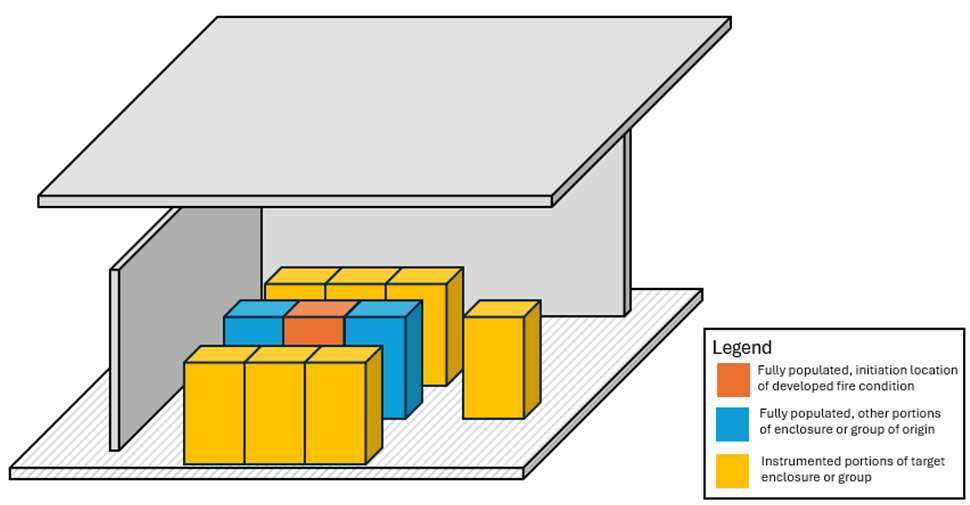 Figure 1: Indoor Floor-Mounted LSFT Test Layout — Elevation View
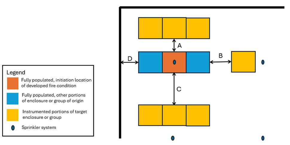 Figure 2: Indoor Floor-Mounted LSFT Test Layout — Plan View (with Fire Sprinkler System Schema)
3.3 Fire Initiation Methods & Developed Fire Definition
Fire must be initiated at the vertical/horizontal location determined by structural review to produce maximum thermal stress (typically the bottom-most vertical module location near outer boundaries). Approved initiation mechanisms include:
Heater Board + Auxiliary Ignition Source (spark plug/igniter placed in gas vent path).
Electrical/Mechanical Abuse + Auxiliary Ignition Source (overcharge/short-circuit + igniter).
Gas Burner (direct diffusion or premixed burner).
Definition of Fully Developed Fire:
Outdoor Setup: Thermal runaway and active flaming propagation across at least one full vertical column (rack) of modules within the Enclosure of Origin.
Indoor Setup: Complete thermal runaway propagation across at least one full module and complete ignition of all combustible materials within that module.
4. Quantitative Pass/Fail Criteria (Indoor vs. Outdoor)
To pass UL 9540A LSFT, the test array must meet strict empirical boundaries outlined in Edition 6:
| Evaluation Metric | Outdoor LSFT Requirement | Indoor LSFT Requirement |
| Target Unit Thermal Runaway | Zero cell thermal runaway or gas venting in Target Enclosures. | Zero fire spread across aisles; confined to Enclosure of Origin or immediate vertical column. |
| Target Cell / Module Surface Temp | ≤ Mean gas venting temp measured in Level 1 (Tvent). | ≤ Mean gas venting temp measured in Level 1 (Tvent). |
| Target Enclosure Interior Surface Temp | ≤ 110% of Level 1 mean gas venting temp (1.10 × Tvent). | ≤ 110% of Level 1 mean gas venting temp (1.10 × Tvent). |
| Wall Structure Temp Rise | —— | Temp rise ≤ 97℃ (175℉) above ambient. |
| Ceiling Structural Steel Temp | —— | 1-minute average temp ≤ 538 (1000℉). |
| Incidental Radiant Heat Flux | 60-second moving average ≤12.5 kW/m2. | 60-second moving average ≤12.5 kW/m2. |
| Structural Integrity & Debris | No structural collapse over 24-hour post-test. | No structural collapse over 24-hour post-test; flying debris ≤ 1.5 m. |
Temperature Tolerance Clause (6th Edition Update): All temperature data must be processed using a 60-second moving average. For thermocouples on module casings or interior enclosure walls, temperatures may exceed the specified limit for a cumulative duration ≤5 minutes, provided the peak does not exceed 120% of the allowable threshold.
5. Specific Rules for Stacked BESS Installations
For multi-tier stacked BESS deployments (e.g., modular commercial/industrial storage or dense data center UPS systems), UL 9540A Edition 6 mandates:
Target units placed both horizontally adjacent and directly above the Enclosure of Origin.
Full mechanical rated weight loading applied during the test.
Dedicated thermal sensors mounted on the underside of the upper stacked cabinet.
24-hour structural observation post-test to verify zero frame collapse.
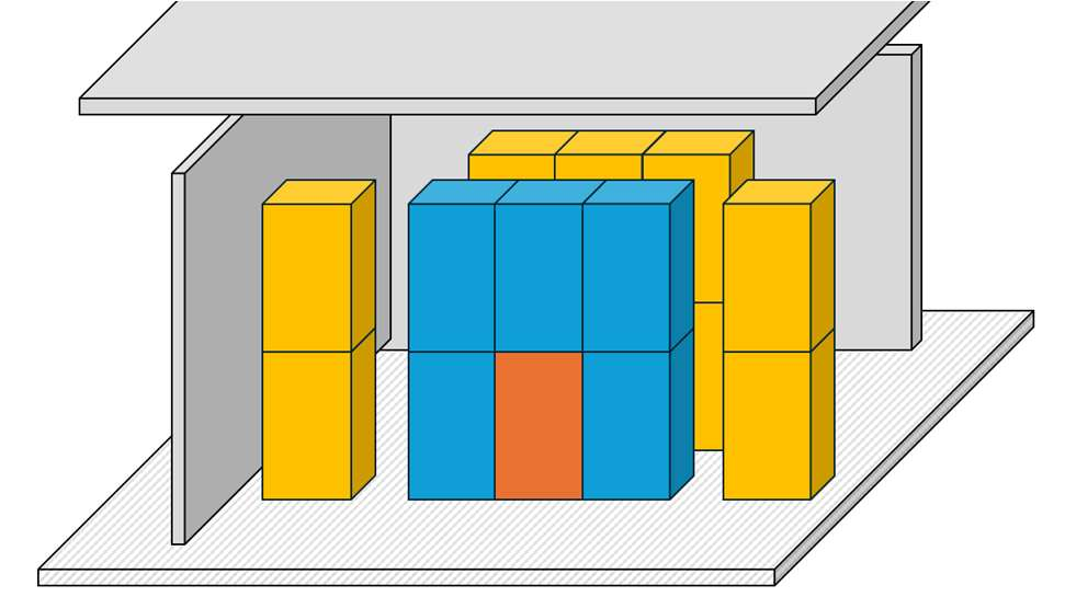 Figure 3: Schematic Layout for Stacked BESS Large Scale Fire Testing
6. Test Termination & Post-Fire Observation Requirements
An LSFT test cannot be concluded immediately after flames die down. Official termination requires fulfilling all conditions below:
Complete extinguishment of open flames inside and outside the Enclosure of Origin.
Internal temperature of the Enclosure of Origin stays below 100°C (212°F) for at least 3 continuous hours.
Target enclosure temperatures show a continuous downward trend below threshold limits for at least 3 continuous hours.
Active Suppression Observation: If water-based sprinklers are used, a mandatory 12-hour observation period begins after shutting off water supply to verify zero thermal re-ignition.
Structural Integrity Window: Stacked configurations require 24 hours of post-test observation.
7. Frequently Asked Questions (FAQ) for Overseas Buyers
Q1: What is the difference between UL 1973, UL 9540, and UL 9540A?
UL 1973: Standard for stationary battery packs/modules (evaluates electrical, mechanical, and environmental safety of the battery pack itself).
UL 9540: System-level safety certification for the complete Energy Storage System (including inverter, BMS, thermal management, and enclosure).
UL 9540A: A test method (not a pass/fail certificate) that generates thermal runaway, gas venting, and fire propagation data required to achieve UL 9540 system certification and NFPA 855 installation approval.
Q2: Do commercial and industrial (C&I) or residential BESS projects always require Level 4 LSFT?
Under NFPA 855:2026, if you plan to install BESS units with individual capacities exceeding threshold limits (20 kWh for Li-ion) or reduce the default 3 ft (0.91 m) separation distance between units and wall structures, UL 9540A LSFT test data is legally required by the local Authority Having Jurisdiction (AHJ).
Q3: How do UL 9540A requirements impact special vehicle/industrial equipment batteries (e.g., forklifts, AGVs, sweepers, marine, RVs)?
While motive power and industrial vehicle batteries are primarily governed by standards like UL 2580 (EV batteries) or UL 2271 (Light EV batteries), buyers specifying heavy-duty lithium power units for indoor industrial use (e.g., automated warehouse AGVs, medical cart fleets, marine ESS) increasingly request UL 9540A Level 1 & Level 2 gas venting and flame propagation data to ensure indoor thermal safety and explosion venting compliance.
Q4: Can a manufacturer be exempt from Level 4 (LSFT) testing?
Yes. Exemption from Level 4 testing is allowed under UL 9540A Edition 6 if Level 3 (Unit Level) testing demonstrates that thermal runaway, flaming, and combustible gas egress are entirely contained within the single cabinet enclosure without external flame egress or surface temperatures exceeding safety thresholds.
Q5: Does a UL 9540A test report expire?
UL 9540A test reports do not have a fixed expiration date. However, if a manufacturer modifies battery cell chemistry (e.g., switching cell suppliers or chemistry ratios), module layout, BMS protection thresholds, or cabinet structural materials, re-testing or engineering evaluation under the latest version (Edition 6) is required by certification bodies.
Q6: Why do North American buyers specifically ask for "UL 9540A 6th Edition" compliance?
Edition 6 harmonizes directly with NFPA 855:2026 and International Fire Code (IFC 2024/2027). Importing or installing BESS units tested under obsolete 4th or 5th editions may lead to rejected building permits or failed fire marshal inspections during site commissioning in North America and Western Europe.
Our expert will reach you out if you have any questions!